Geothermal Heating and Cooling

A geothermal heating and cooling system circulates a water-based solution through a buried loop system in the ground to take advantage of these constant temperatures.


IT takes Geothermal Technology to Dig Into Energy Efficiency


WaterFurnace® geothermal heating and cooling systems tap into the Earth’s surface to use thermal energy found underground, or in a pond or well water. Geothermal heat pumps are able to maintain very high efficiencies on even the coldest winter nights or the hottest summer days, to save energy and money.

When it comes to heating and cooling solutions, geothermal systems are extremely efficient. These packaged systems work quietly to deliver comfort in variable speed Preferred™ models or the multi-speed Legacy™ line. With the evaporator coil, condenser and compressor all in one cabinet, you can evenly heat or cool large homes easily.

Loop Fields (Examples & Descriptions)


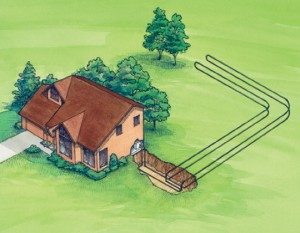
Horizontal Closed Loop Example

Horizontal Closed Loop

Horizontally-excavated or trenched ground heat exchange systems require the most surface area for buried closed-loop GHEX applications, but they are usually the most economical first-cost option compared to vertical or horizontally-bored systems.  Due to the extensive excavation normally required, available space is generally the limiting factor.  Shallow rock can be challenging also.

The “original” horizontal GHEX consisted of a single pipe loop buried inside a long, narrow trench at some depth underground.  Through this pipe water was circulated to and from the heat pump, extracting or rejecting heat geothermally as required during heat pump operation.  Adding antifreeze to the water inside this closed loop extended the low operating temperature range of the system below the frost point and protected the heat pump water coil from icing or cracking during winter operation.  It also allowed for a shorter loop to be designed, potentially lowering installation costs.

Soon it was found that layering a longer single pipe back-and-forth at varying depths inside an even shorter trench further reduced space requirements and cost without necessarily sacrificing geothermal capacity.  By combining multiple pipe loops in parallel on a single consolidated pipe manifold, larger capacity systems could also realistically be achieved.

These evolving approaches were primarily aimed at maximizing system performance at minimal space and installation expense, and they established a practical basis for the way horizontally-excavated GHEX design and installation is approached to this day–with a wide range of variations.

In a climate where frost depths reach 4 to 7 feet, horizontal GHEX piping systems are better laid flat on the bottom of a wider machine-excavated trench, or open pit, dug at least two feet below the deepest annual frost.  Open pit excavations are often chosen in soils where caving might occur inside a narrower (e.g., bucket-width) trench, which can severely compromise an application.  To help minimize excavation costs and conserve space with limited sacrifice to system performance, horizontal GHEX designs tend to utilize longer pipe lengths–coiled into more dense arrays–inside a smaller excavation footprint than a single straight pipe would normally require.

As a general practice, the number of individual pipe coils used in the GHEX assembly will be the same as the nominal ton capacity of the GHP–that is, a 6 Ton heat pump would utilize 6 coils of equal length in the GHEX.  One coil per trench is the rule of thumb.  Coils are connected together in parallel on a common supply-return header (manifold).  On larger systems, not more than 10 coils usually share the same header before splitting the total number of coils between two–with a few exceptions.  The diameter of the HDPE pipe used for coils is usually  3/4″ or 1″ with larger diameters used for headers.

Trenches are commonly dug 6′ to 8′ deep and up to 150′ long (100′ is typical) with a common header trench shared by all.  Spools of pipe containing 500 to 800 feet each, determined by design, are used for each trench coil.  They are sometimes rolled out back-and-forth along the full length of the trench several times in a linear, evenly spaced “racetrack” fashion…or spread out like a deck of cards from one end of the trench to the other in a radial “slinky” fashion.  In either case, both pipe ends of the coil wind up at the same end of the trench for application of the header.  Coil spacing and number of runs are determined by design.

In open pit applications, excavation footprint and coil placement tends to be more consolidated than with spaced trenches.  Depth remains approximately the same, but open excavations often afford greater versatility in conforming to irregular property shapes and dimensions.  Excavation footprint is approximately 400-500 sq. ft. per ton in Michigan, depending on space requirements and soil conditions.

For optimum heat transfer, saturated or even moist soils–found frequently in lower areas–are much preferred over dry.  In drier soils, increasing the design loop lengths and/or spacing can often compensate for lower heat transfer rates.  So can the introduction of a soaker piping system placed directly above the GHEX coils, where rain or surface water may be periodically diverted.  Such considerations are generally given to the specific conditions found at each site.

Pond Closed Loop Example

Pond Closed Loop

It may seem counter-intuitive to many that a modest backyard pond capped with a thick layer of winter ice might serve as an adequate geothermal heat source through an entire Michigan heating season, but this possibility may be well worth exploring on sites which have such a resource available.  Like a buried closed-loop system, a pond loop uses a “sunken” closed piping system through which an antifreeze-water solution is circulated to perform heat exchange between the geothermal pond heat exchanger (PHEX) and heat pump.

A pond loop may be designed and constructed in many different ways, but the underlying principal remains the same for all: Water in its “heaviest” state is 39 deg. F. and tends to rest in its own isolated temperature layer at the bottom throughout the year.  This is where the PHEX is ideally placed.  In winter, as heat is extracted from the 39 deg. water around the loop coils, the water cools and ascends by way of its own convective current upward toward the surface.  This draws in “fresh” ambient 39 deg. water from the thermocline directly around the PHEX.  Similarly in summer, as heat is rejected, the warmed water also migrates upward away from the PHEX as cooler ambient water is drawn back in around it.

Most often, the same type of HDPE pipe materials that are used for earth loops are used for pond systems; however, pipe length requirements per nominal ton tend to be significantly shorter–and coils can usually be configured in a more compact arrangement–than with buried systems.  In some cases, spools of pipe from the factory are simply fitted with intermittent spacers between the pipe layers to allow convective water flow between them.  Sometimes coils are loosely spread inside some sort of containment or “cage” constructed with galvanized wire mesh material…or they are simply spread out flat in a consolidated slinky array.  In each case, the PHEX is usually constructed on shore, somehow lightly weighted (air inside the pipe coils should still keep them moderately buoyant), floated into the pond, and sunk during system filling.  The supply-return header pipes are then buried inside a trench below frost from the pond to the building.

Variations of PHEX construction include the use of copper tubing (instead of HDPE) and a modular type of stainless steel “plate” heat exchanger that is specially manufactured.  In Michigan, it is also possible to apply for a special permit through the DNR for construction and placement of a geothermal “lake energy exchanger”…but only if there are no other geothermal loop options on the property.

Proper loop design, as well as pond size and depth requirements, are specific to each application; only a qualified and experienced geothermal designer or contractor should be consulted, beginning with whether or not a pond is even suitable enough to function as a geothermal heat source.  A properly designed and installed pond system can usually reduce closed-loop installation costs, increase system performance, and offer an appealing aesthetic component that an earth loop cannot provide.  But an inadequate pond loop design can lead to mass temperature degradation and thermally resistant ice caking around the PHEX coils, potentially rendering the system completely inoperable for whatever might remain of winter.

Vertical / Horizontal Boring Closed Loop Example

Vertical / Horizontal Boring Closed Loop

Vertically-bored ground heat exchange systems require the least amount of surface area for buried closed-loop GHEX applications.  They are typically the most expensive of all of the closed-loop options, but are sometimes the only one feasible depending on available space, site geology, and system design requirements.  While vertical GHEX designs may vary widely, a general rule of thumb is to utilize one borehole per nominal ton of GHP capacity drilled 150 to 250 feet deep, with 15 to 25 foot spacing between boreholes.  Longer drilling depths are possible to reduce the number (or spacing) of boreholes…and shorter ones in greater numbers may be used if shallower drilling conditions require it.

Most commonly, a single loop of pipe with a U-bend at the end is placed down the length of each borehole, which is then back-filled bottom-up with a special grout to enhance conductivity and seal it against aquifer erosion.  Multiple U-bend pipes per hole are also possible if some additional thermal capacity is needed due to certain site limitations.  Each vertical pipe is then connected to a horizontal header piping system, which is buried 6 to 8 feet underground with supply-return pipes to and from the GHP.

In Michigan, proper sizing, design, and installation are critical to vertical GHEX performance and seasonal loop field recovery…especially on northern “heat only” hydronic GHP applications where the exclusion of summer geothermal cooling–often by design–does not allow for the rejection of heat back into the loop field between heating seasons.  Also, on rock-bored applications, Michigan law requires that a permanent well casing be applied to each borehole along any “unconsolidated” overburden (soil) between the bedrock and surface.  While a casing is not required in unconsolidated only formations, depth to bedrock can often make or break a vertically-bored project due to cost.

HORIZONTALLY-DRILLED SYSTEMS:

Horizontal directional drilling (HDD) is becoming a much more common method for the placement of geothermal ground heat exchangers.  Horizontally-drilled systems mimic vertically-bored applications in almost every aspect (including the application of grout) except that they are horizontal.  The method is often simply described as “a vertical system set on its side”…which also means that it will generally require a much bigger lot size than a vertically-bored–or even horizontally-trenched–system, since everything must fit horizontally beneath the property.

Minimum length required is approximately 225 feet of U-bend loop per nominal ton of heat pump capacity at minimum depth and spacing of 15 feet…although on a smaller lot it is possible to drill two or three shorter holes and combine them as one–or even stack them vertically (e.g., at horizontal depths of 15, 30, and 45 feet).  On larger properties where much longer HDD boreholes can be drilled, it is possible to utilize a smaller number of holes to achieve sufficient geothermal capacity.

One benefit of horizontally-drilled systems over other methods is that they can be installed under structures, lawn and garden obstacles, play fields, etc., without disturbing those existing structures.  This often provides access to ground heat exchange areas that would not otherwise be available.  Horizontally-bored systems can also be installed at lower cost in areas where depth to rock is shallow and the economics of drilling into the rock or drilling shallow boreholes to stay above the rock make a vertically-bored system more cost prohibitive.

Open Loop aka “Pump & Dump” Example

Open Loop aka “Pump & Dump”

Open Loop systems, popularly called pump-and-dump, use plain domestic well water as the heat source for the geothermal heat pump (GHP) system.  No buried closed-loop ground heat exchanger (GHEX) is actually used.  Installation is often as simple as tee-ing directly into an available domestic water pipe in the basement and plumbing it to the GHP…then running a discharge pipe from there to some location on the property where the “used” geothermal water may be dumped directly into a drainage ditch, tile, or pond. Larger residential or commercial systems may be slightly more sophisticated, but the principle remains the same for all: Heat is extracted (or rejected) directly to (or from) the well water during GHP operation.

By eliminating GHEX material and installation costs, open loop systems generally have a significant first-cost advantage over closed loop systems. They also tend to operate at higher efficiencies than closed loops in Michigan due to higher entering water temperatures during winter GHP operation and cooler temperatures during summer.  Well capacity, recovery rate, temperature and quality–as well as water discharge opportunities on the site–are the general limiting factors.  Some periodic back-flush cleaning of the internal GHP water coil may also be necessary to remove mineral deposits.

Michigan Considerations: The Michigan Department of Health (DOH) and Department of Natural Resources (DNR) should be consulted on all well water and water usage concerns involving open loop systems. Following are some basic considerations:

Due to relatively high water usage volumes during peak seasonal operation of an open loop system, local aquifer draw-down may be of concern in some areas; it may be of less concern in others where the aquifer may be more viable or where discharge water may be quickly returned to it.  Local well drilling contractors and DOH officials are usually very helpful in determining this.

Smaller residential-sized systems in Michigan generally fall within the currently specified water usage limits of 10,000 gal. per day and 1,000,000 gal. per year without requiring a permit.  Any system exceeding these limits does require application to the DNR for a special water use permit.  Also, discharging ground water directly into public surface water is not allowed; but it is permissible to discharge directly on top of the ground–as with lawn sprinkler systems–or to discharge into a private holding pond, subsurface drain tile, or leach bed (no deeper than 15 ft.).

A variation of the pump-and-dump system, which is also allowed in Michigan, is one which pumps water directly from a lake or large pond then dumps it directly back during GHP heating and cooling operation.  However, lake water quality and, more particularly, cold winter water temperatures impose some limitations on such applications in the northern climate.

Reinjection Wells: Although it will incur additional installation expense, it is possible to obtain a variance for a separate well to be drilled for the purpose of re-injecting water back into the same aquifer from which it was originally drawn.  This may be the only option available on sites where other discharge opportunities do not exist.

Standing Column Wells: Coming into some use in Michigan (albeit with mixed results) is the standing column reinjection well, which utilizes a coaxial heat exchange system inside a single domestic water well.  Water is drawn from the bottom of the well through a “standing” thermally resistant pipe and is re-injected back into the annular space between the pipe and the surface of the borehole where heat exchange can occur as the water is recycled back to the bottom during GHP operation.  This type of system is limited mainly to solid rock formations and requires precise engineering.  It may be the only option in some circumstances where available space and surface discharge opportunities are completely limited and it is sometimes considered as a last resort.

Get A Quote Now!